 |
VR-Forces 4.6.1 Class Documentation
|


All Classes Namespaces Files Functions Variables Typedefs Enumerations Enumerator Properties Friends Macros Groups Pages
|
VR-Forces 4.6.1 Class Documentation
|
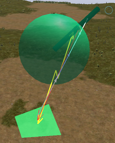
You can use the Remote Draw API to create 3D lines, cylinders, cuboids, ellipsoids, and triangles.
You can place text on the overlay based on a 3D location. All 3D positions can be specified in any one of the following ways:
When you attach to a line or cylinder draw control object, which itself has two positions, the position of attachment can be specified as a percentage between the two positions that make up the object being attached to. All coordinates, positions, offsets, diameters, and so on are specified in meters unless otherwise indicated. Rotations are in radians about the geocentric axes (as with normal DIS and HLA/RPR objects).
All 3D positions are specified using a DtVdc3DAttachPoint. The DtVdc3DAttachPoint provides a single class that can represent and manage all the different types of placement into the 3D scene.
The following example creates an attachment point in Geocentric coordinates:
To modify the y-coordinate using the DtVdc3DAttachPoint, do the following:
DtVdcLine3DObject represents a line that can be positioned and displayed in the scene. The line can be divided into multiple segments of varying relative lengths. A color, line style, arrow style, pattern, and thickness can be specified for each segment. The line can flash. The line can be offset from its specified position. Optionally, the line can be terminated if it intersects any intervening terrain. In other words, the line can go from the start point to the end point or the first point at which it intersects the terrain, whichever comes first. Each endpoint of the line can be positioned using any of the member functions described for DtVdc3DAttachPoint.
The following example creates and displays a 3D line that goes between two entities whose IDs are in the variables globalId1 and globalId2, respectively.
The following example creates and displays a second 3D line that goes from the center of the line created in the previous example to a third entity, whose ID is held in the variable globalId3. It indicates that the line should terminate if it intersects the terrain.
DtCylinderObject allows you to specify the attachment, shape, rotation, and color of a cylinder on the screen. You can also make the object flash. You can:
The diameters of the cylinder in the X and Y directions are specified in meters, using a DtVdcVector2D.
The following example creates and displays a cylinder that goes between two entities whose IDs are in the variables globalId1 and globalId2 respectively. It gives the cylinder a circular cross section with 0.5 meter diameter.
The following example creates a second cylinder that is ten meters long. It is two meters in diameter in the X direction and one meter in diameter in the Y direction. Its center is at a point five meters above the center of the first cylinder.
DtCuboidObject is used to create cuboid objects (also known as rectangular parallelepipeds). The attachment parameter specifies the center of the cuboid. A length, width, and height must be specified. The cuboid can be offset from its initial attach point and rotated. You can specify a color and flash behavior.
The following example creates a semi-transparent yellow cube with 1.5 meter sides at a specified geocentric location.
DtEllipsoidObject is used to create ellipsoids (including spheroids and spheres). The attachment parameter specifies the center of the ellipsoid. You must specify the diameters in each dimension. The ellipsoid can be offset from its initial attach point and rotated. You can specify a color and flash behavior.
The following example creates and displays a light blue ellipsoid with a length of ten meters and equal height and width of three meters. It is attached to the end of a previously defined cylinder.
DtTriangle3DObject is used to create triangles positioned in the scene. These triangles are not projected onto the 2D overlay, so 2D effects like fill patterns are not supported. You must specify the vertices of the triangle. Attachment to simulated entities or other Draw Control objects is not supported. The triangle (outline) can be drawn in any color, and can flash.
The following example creates and displays a green triangle.
DtArea3DObject is used to create area objects. A std::vector of DtVector vertices must be passed in. These vertices must be specified in geocentric coordinates, in counterclockwise order, must be coplanar, and must specify a convex polygon. You can specify color, texture, and flashing for the area. Texture parameters include a texture directory, a texture file name, and a tiling parameter, which specifies the number of times in each dimension the texture is tiled on the area.
The following example creates the specified four-point area with a texture, tiled 10x in each direction.
Text can be positioned in the 3D scene and then projected onto the 2D overlay using DtText3DObject. The lower left-hand corner of the text can be positioned in 3-space using DtVdc3DAttachPoint. It can also be offset from that initial position in scene coordinates. The text is then projected onto the 2D overlay, so it is not occluded by terrain. You can set color and flashing attributes.
The following example creates and displays 3D text with the message "Your text here!" one meter above an existing Draw Control ellipsoid. It is blue and flashing.
[<< 2D Objects] [Home] [Top of Page] [Attributes >>]