 |
VR-Forces 5.0.1 Developer's Guide
|


All Classes Namespaces Files Functions Variables Typedefs Enumerations Enumerator Properties Friends Macros Groups Pages
|
VR-Forces 5.0.1 Developer's Guide
|
The Custom Control Object example adds a new control object to the create menus and creates and associates a new dialog box to use during creation and editing of this new control object.
The new control object and its dialog boxes are area-type objects and its classes are derived from the Area control object. 4 custom parameters are associated with the new control object. 2 at the state data level defined in the .ope file and configurable before creation either in the .ope file or in the Simulation Object Editor, and 2 at the runtime creation via the definition dialog which will be stored as userData.
The front-end example demonstrates the following:
Objects get assigned to the object creation palettes based on information in their .entity file. The information comes from the settings chosen in the Simulation Object Editor. Specifically, objects get placed on a palette based on the gui-on-palettes parameter. If this parameter is not specified, objects get placed on a palette based on their entity type enumeration. Objects with a kind value >= 16 get placed on the Tactical Graphics palette. The custom control object has a kind value of 18. Within a particular palette, objects get organized based on the gui-categories parameter. An object can be in more than one category.
The Custom Control Object example inherits the dialog class structure used by Area control objects (DtShapeObjectDefinitionDialog, DtShapeObjectDefinitionDialogLogic and DtShapeObjectDefinitionDialogCreator), makes certain modifications and additions, and then registers the new dialog creator with the appropriate dialog manager (DtVrfObjectModifierDialogManager), associating it with the specific entity ID associated with the new control object.
DtCustomControlObjectDefinitionDialog, derived from DtShapeObjectDefinitionDialog, is ultimately derived from the Qt class QDockWidget. As such, it must be registered with Qt as a Q_OBJECT during compilation. Its specific role is to handle the placement and registration of GUI elements and transportation of data to and from these GUI elements. The Dialog class intantiates its own Logic class, DtCustomControlObjectDefinitionDialogLogic upon intialization.
DtCustomControlObjectDefinitionDialogLogic, derived from DtShapeObjectDefinitionDialogLogic, mostly acts as the interface between data from the DtCustomControlObjectDefinitionDialog and data in the rest of VR-Forces. In particular in this example, the Logic class translates betwen Parameter One and Parameter Two (an int and double, respectively) and userData, the std::string that they are stored in.
DtCustomControlObjectDefinitionDialogCreator is a class consisting only of a simple creator and initialization function that is registered with the Dialog Manager and called when the user invokes the creation or edit of the custom control object.
Adding an attribute to an entity can be done at the configuration stage which requires a little more work or at the runtime createion stage using the generic userData parameter. In order to expedite the process of adding attributes or parameters to control objects in VR-Forces, all control objects have a field of string type referred to as userData. This field is fully implemented but not used by stock VR-Forces.
The custom control object example introduces two custom parameters to the control object type, an int and a double (labeled as "Integer" and "Double" respectively). These parameters are transformed to and from a token-separated string by the Logic class and sent on to be stored in the control object's userdata field.
Naturally, extensive use of userdata must be carefully monitored to ensure that different implementations of userdata do not interfere with each other.
While userData is a quick way to add any kind of value, one does have to parse it and it is only available at runtime. If one wants to allow a user to configure custom parameters before VR-Forces is loaded one can add state data Add State Property example shows how to add, access, and set state data. The cusstom control object instead shows how to display that state data in the Simulation Object Editor allowing user to have a graphical means of editing the values. This avoids having users hand edit files which is error prone and state data defines its type in the .ope file, no string parsing needed.
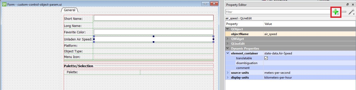
Inside the custom control object simulation model set is a new Area_Object.ope in the platforms folder. It has an additional 2 state-data parameters added to it, a string parameter, Favorite-Color and a double parameter, Air-Speed. To avoid having to hand edit changing these parameters, the example shows how to add them to the Simulation Object Editor. There is no code to be written for this part!
For each line edit widget the green + button was clicked to add dynamic property of type string with name "element_container" was added. For the value add "state-data.your_parameter_name". This will allow the DtUiForParameter class to the state-data list in the .ope file and then look up the specific state data parameter "Your-Parameter-Name". Note the - vs _. The ui element class automatically changes _ to - when looking up the state data name. Or you don't have to use them but make sure yourParameterName has no spaces or other special characters. For parameters with units source and display unit dynamic properties can be added as shown in immage
In the Launcher, click the Plug-ins button to bring up the Plug-ins Selection dialog. Enable the plugin.
To view the new behavior:
The code for the three classes referenced in the table are here: Custom Control Object Dialog.
| DtCustomControlObjectDefinitionDialog | The Qt-derived dialog class. |
| DtCustomControlObjectDefinitionDialogLogic | The logic class providing processing and transport of data to and from the dialog class. |
| DtCustomControlObjectDefinitionDialogCreator | The creator function for the dialog class, registered with the entity modification manager (DtVrfObjectModifierDialogManager). |